A New Generation of High-performance Power Integrated protection Module HMP300

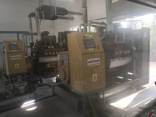
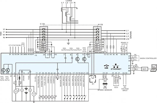
HMP300-2 Power Integrated Protection Module was used for the main distribution board of 50000DWT Bulk Cargo Ship

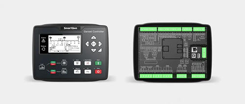
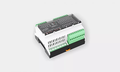
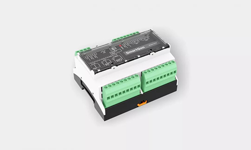
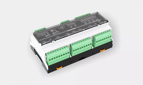
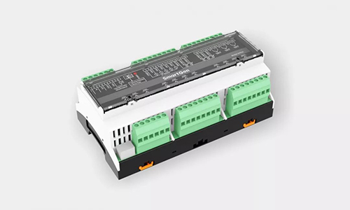
HMP300 power integrated protection module is a high-performance control module developed by SmartGen in combination with the design requirements of marine power distribution system, which integrates the measurement and collection of parameters such as voltage, current, frequency, power and power quality of the generator, abnormal protection and communication transmission functions. It has been certified by CCS and was widely used in marine and land power distribution.

This series of module can be configured at the most four programmable output ports and and two programmable input ports, the designers with a HMP300 control module can reach ever need voltage protection, current protection, reverse power protection and frequency protection and voltage/current harmonic distortion rate and the electrical parameter collection that may kinds of single function module to achieve technical index, can protect diesel gensets, axle gensets and emergency gensets, significantly increase the system integration and cost-effectiveness ratio of AMS and the PMS system structures.

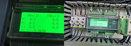
The harmonic detection function of HMP300 series control module

There are two submodels HMP300 and HMP300-2 designed for users to better meet different technical requirements:

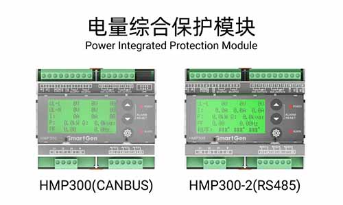
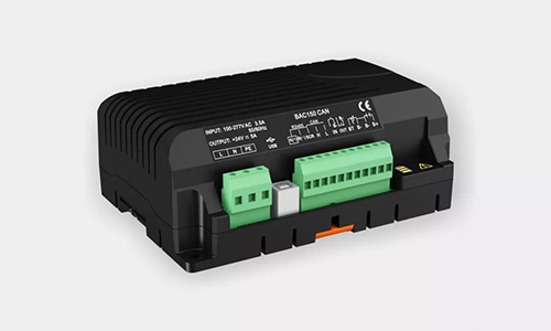
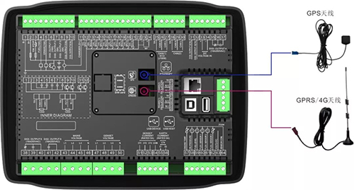
HMP300 is equipped with a communication interface supporting CANBUS2.0B protocol, which is mainly used to communicate with the marine engine control module of SmartGen to achieve power data acquisition and display; The model also has differential protection, which can be used to protect the three-phase leakage current of generator or motor.

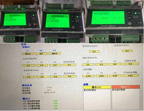
Differential Protection Mode of HMP300

HMP300-2 is equipped with RS485 interface supporting Modbus-RTU communication protocol, which is mainly used for generator and bus protection and transmission of information to the main logical control unit, and supports the function of customizing Modbus-RTU communication protocol. In addition, HMP300-2 is specially optimized for the protection of steady-state frequency fluctuation and transient frequency fluctuation of the axle geneset. Users only need one HMP300-2 to protect all the electrical parameters of the axle genset.

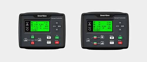
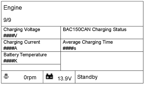
The backlight LCD (132×64) on the module can visually display the values of various electrical parameters and alarm information, and supports display Chinese and English. Users can switch the display interface and modify the core configuration parameters by touching the button.

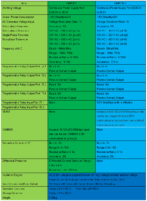
Technical parameters of HMP300 series control module

Application example of HMP300-2 protection shaft belt genset

To help you better understand the design concept of the module, the following are some examples of parameters of HMP300-2 used in the protection projects of shaft belt genset: AC400V50Hz, 450KW, steady-state frequency fluctuation ±5.5%, 10s; transient frequency fluctuation ±11%, 5s.

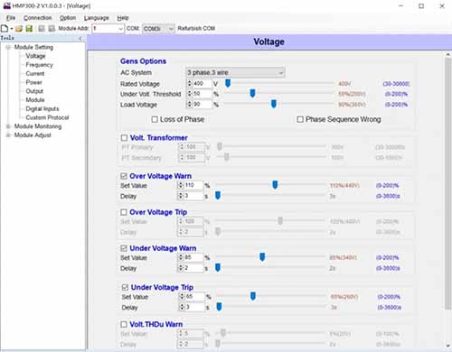
Voltage Protection Parameter Setting

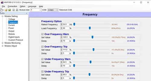
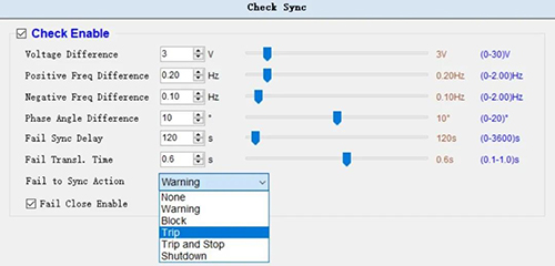
Frequency Protection Setting

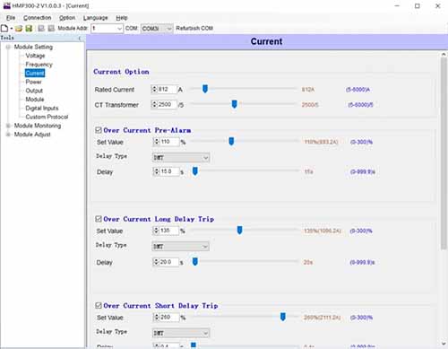
Three-stage Overcurrent Protection Setting

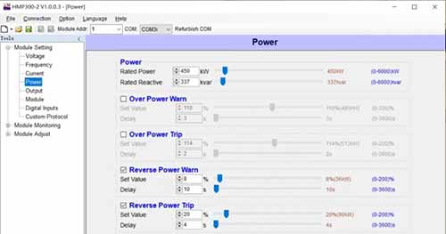
Reverse Power Protection Setting

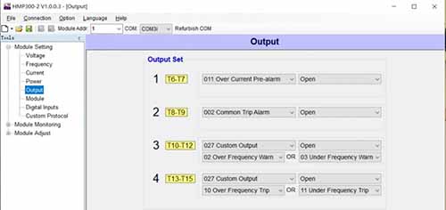
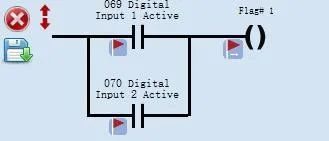
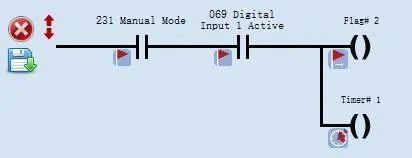
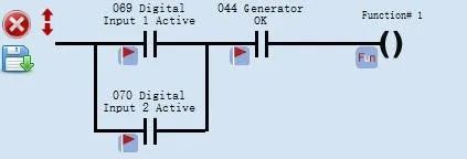
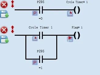
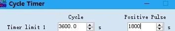
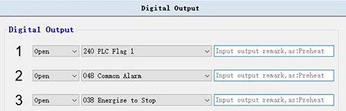
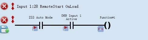
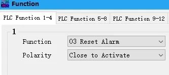
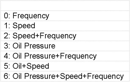
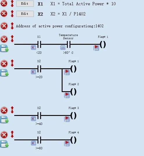
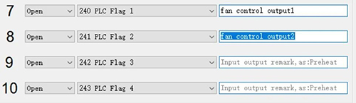
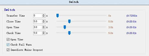
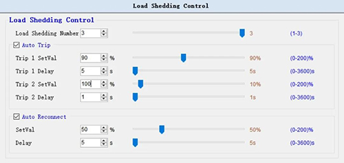
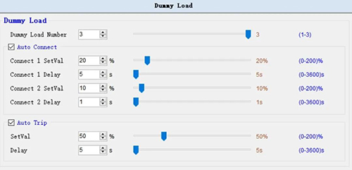
Programmable Output Port Setting

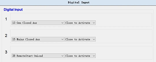
Digital Input Port Setting

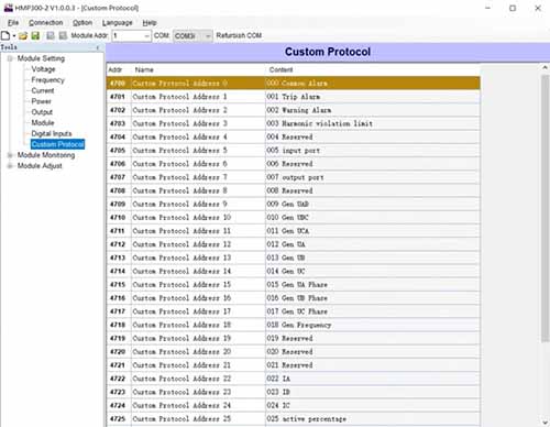
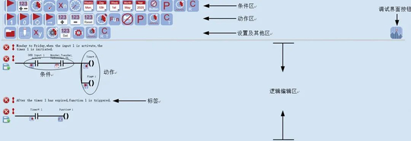
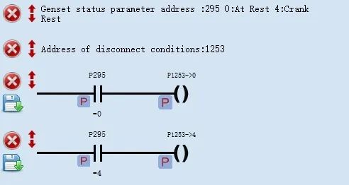
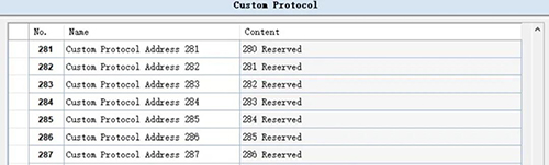
User-defined Communication Protocal Setting

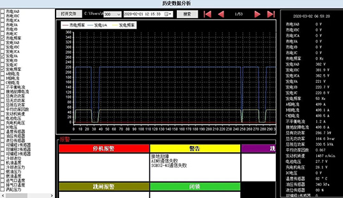
Harmonic Detection (HMP300-2 can detect odd harmonics of 3~31)

We also develop relays used for voltage, frequency, current, reverse power with single function and multifunctional protections, while in order to facilitate on-site debug and parameters configuration, SmartGen developes a special PC test software for each control module, users can access to relevant information from our website for free.

Information address for HMP300 power integrated protection module:

Information address for HMP300-2 power integrated protection module:

Information address for HPD300 reverse power protection relay multifunction protection:

Information address for HVD300 voltage detection multifunction protection:

Information address for HOC300 overcurrent protection relay multifunction protection:

Information address for HFT300 frequency detection relay multifunction protection:

www.smartgen.cn

Good News: HGM6100 Series Genset Control Modules Passed UL Certification Authentication

Congratulations~ HGM6100N series genset control modules has passed UL certificate authentication! The products meet standards of UL and CSA.

HGM6100N control modules has six variants

HGM6110N/6110NC/6110CAN
Automatic sart module, it controls genset to start/stop by remote start signal.

HGM6120N/6120NC/6120CAN
Based on HGM6110N/6110NC/6110CAN, it adds mains AC monitoring and mains/genset automatic switching control (AMF), especially suitable for the automation system composed by mains and genset.

lease identify the trademark and purchase channels.
Improving quality and competitiveness is always our driving force!

www.smartgen.cn

Here are functions you need (Chapter 5)—HGM9420N/LT

In the previous four chapters, we respectively introduced the powerful display functions of HGM9420N/LT (with 16 built-in languages), as well as various extensions, synchronization switching, communication protocol customization, NEL((non essential load), dummy load, cloud monitoring, PLC, etc. This chapter we will introduce the functions and application methods of USB interface.

There are two kinds of USB interfaces of HGM9420N/LT. The USB drives in FAT32 format can be inserted through the Host USB interface to achieve the following functions.

Input or output of configuration parameters

1. Press for more than 1s,then go to user menus of the following table.

2. Select the USB flash drive configuration with reading and writing, which could check, download, save and renew the configuration file.The configuration file suffix is.lgm.

3. Check the xxx. lgm configuration parameter file in the USB flash drive.

4. Download the configuration file in HGM9400NXXXX. lgm format to the control module.

5. Save the control module’s configuration parameters to the corresponding HGM9400nxxx.lgm file.

6. Renew configuration file(HGM9400NXXXXX.lgm).

Historical Data Storage

The historical data is stored with year/month as the folder name and year/month/day as the .dat file name. The unit stores data once per minute in standby mode and once per second in other states. If the storage space of USB flash drive is less than or equal to 200MB, the earliest one-month data files stored will be deleted.

The historical data files are shown as below.

Curve of historical data

The curve of historical data could be checked and viewed by the “data analysis” function of iGMP6 test software.

In the previous chapters, we have introduced the main functions of HGM9420N/LT. If you have any questions or further demands of the control module, please feel free to contact us!

Go, genset control!

Go, China!

www.smartgen.cn

The world has kissed my soul with its pain, I would like to sing a song for its return

China is undergoing with great trials and tribulations of the epidemic. From the initial spread to the present basic control, Chinese people have done their best.

Strictly following the requirements of protection measures, actively responding to the outbreak, while ensuring that the resumption of production, we are always in action!

The Dubai exhibition was held as scheduled and ended successfully. Service is on schedule even in special time.

SmartGen is always with you, always your trusted partner! We’re always here.

www.smartgen.cn

Parrallel and Grid-connection Application of Gas Genset

This case involves the use of SmartGen’s HGM9510 parallel control module that can realize multi-units parallel connection; HGM9560 multi-units grid-connection control module can realize parallel connection of power generation and mains supply. With the cooperation of the two, it can meet the requirement of multi-units parallel connection and grid-connection with mains supply, realizing the application of the constant power output and the shear peak of the units.

The operation data of the two units are as follows

The first unit, accumulative power: 1204.4 MWH; power factor: 0.89; accumulative running time: 10,528 hours.
The second unit, accumulative power: 795.4mwh; power factor: 0.77; accumulative running time: 10,528 hours.

Site Photos

Grid-connection diagram of the two units

Constant power output: the maximum active power output of the genset is what the setting active power output of the geneset. When the gensets and the mains supply are connected in parallel successfully, the power generation begins to output the load. When the active power output of the power generation reaches 100%, the remaining load is carried by the mains supply, which can also be considered the power generation as main use. When the load is less than the setting value of active power output of the power generation, the mains supply begins to soft unload tripping.

Mains supply shear peak: mains supply first starts with load, when the active power output reaches 100% of setting value, the control module is in automatic mode, gensets start automatically, closing and paralleling with mains supply after normal operation, units start soft unloading, receiving the rest of load, when the load is lower than the setting value of active power output of mains, the units stops for soft unload tripping.

www.smartgen.cn

The fight against the epidemic is not relaxed in MEE Dubai

In this special time, participating in MEE with high popularity requires not only courage and determination, but also an important inspection whether self-protection reach the standard. Chinese people are fully aware of the harm of the novel coronavirus and its infectivity. Thanks to the joint efforts and self-isolation of the whole nation, the epidemic situation in mainland China has been controlled effectively. But the global trend is not optimistic.

SmartGen arrived in Dubai as promised, without absence and giving up. We adhere to a trust, a promise, a global service concept. We are here for you whenever you need !

Making joint efforts to fight against the epidemic, for a better tomorrow of mankind !

Go, China!
Go, Dubai!
Go, the whole world!

www.smartgen.cn

Here are functions you need (Chapter 4)—HGM9420N/LT

In the previous three chapters, we respectively introduced the powerful display features of HGM9420N/LT (with 16 built-in languages), as well as the various extension, synchronization switching, communication protocol customization, NEL((non essential load), dummy load, cloud monitoring, etc. This chapter we will introduce the PLC function of the control module.

The PLC editing interface is shown as follows

PLC elements: condition elements, action elements, settings and other areas

1. The conditional elements are shown in the following table

2. The action elements are shown in the following table

3. Setting and other areas


Logic Introduction

1. “Or” logic diagram


Description: either the input port 1 or the input port 2 is effective, the mark 1 is set to 1; otherwise the mark 1 is set to 0.

2. “And” logic diagram


Description: when the control module is in manual mode and the input port 1 is effective, mark 2 is set to 1 and the timer 1 begins to counting; Otherwise mark 2 is set to 0, timer 1 reset.

3. Combinational logic example diagram


Description: either “input port 1” or “input port 2” is effective, and “normal output of power generation” is effective, triggering ” performance function 1″.

Applicaion Examples

Example 1: Engie Oil Prelubrication
Engine Oil prelubrication function requirements: when it is standby, output 0.5 hour, stop output 0.5 hour; output during preheating, not during other periods.

1. The PLC logic diagram is as follows


Description: P295 engine state parameter, 0: stands for “standby”; 1: stands for “preheating”.

2. The settings of the control module output ports are as follows

Example 2: Automatic clear stop alarm
Requirements: when the genset is in automatic mode, after the remote start (on-load) input is disconnected, it will automatically clear the alarm.

1. The PLC logic diagram is as follow

2. The control module input port is set as follows

Example 3: Modify the configuration parameters of successful crank conditions
Requirements: the successful crank condition of the unit is power generation + oil pressure. For the first start, the crank condition should be changed to power generation because crank cannot be judged accurately according to the oil pressure. For the second or the third start, the crank condition should be changed to power generation + oil pressure.

1. The PLC logic diagram is as follows

2. Description of successful crank

Example 4: Mutiple fans control
Requirements: when the percentage of the unit’s on-load power is less than 20% and the engine temperature is greater than 60℃, Fan 1 outputs. When the percentage of the unit’s on-load power is equal or great than 20%, Fan 1 and Fan 2 output; when the percentage of the unit’s on-load power is equal or great than 40%, Fan 1, 2 and 3 output; when the unit’s on-load power percentage is equal or great than 60%, Fan 1, 2, 3 and 4 output.

1. The PLC logic diagram is as follows:

2. The settings of the control module output port are as follows

The PLC function of HGM9400N could also realize data acquisition and logic control with CAN interfaces modules (chargers, HAT series control modules, etc.) by customizing CAN communication configuration quantity.
It will be continued…
We will introduce functions and usage of the Host USB interface next time.

www.smartgen.cn

Here are functions you need (Chapter 3)—HGM9420N/LT

In the previous two chapters, we respectively introduced the powerful display features of HGM9420N/LT (with 16 built-in languages) and various extended functions. This chapter we will introduce the single unit control module’s special synchronization switching features, as well as the communication protocol customization, NEL (non essential load), dummy load, cloud monitoring and other functions.

The single unit automatic system composed of one mains supply and one genset could realize the synchronous swithing beween power generation and mains supply, which decreases the power supply interruption to a great extend caused by power generation and mains switching.

Operation Description 

Automatic start/stop
Press

button, the indicator lights on, indicating that the genset is in automatic startup mode.

Automatic start:
a) Mains power is normal and remote start (on-load) is effective, the unit high-speed warming-up delay ends, the indicator lights on if power generation is normal, the control module sends out switch-on signal when gensets and mians power meet the synchronization requirements, while sending out the switch-off signal immediately after detecting power switching feedback signal, then genset is on-load.

b) When the mains power starts abnormally and high-speed warming-up ends, the indicator lights on if the power generation is normal. If the voltage and frequency meet the requirements of on-load, the power generation closes and relay outputs, the genset is loaded, the power supply indicator lights on and the genset is in normal operation.

Automatic Stop:
During the normal operation of the genset, if the mains power returns to normal, then enters the “mains voltage normal delay”. Make sure the mains power is normal, the indicator of mains power status will be on, the “stop delay” will begin. For another case, when the remote start input fails, “stop delay” starts.

The control module waits for gensets and the mains power to meet the synchronization requirements, it will send out the mains power closing signal. After detecting the feedback signal of mains power switch-on, it will immediately send out the mains power switch-off signal, the power supply indicator lights off, the mains power is on-load, the mains power supply indicator lights on, and the “high-speed heat dissipation delay” begins to enter the shutdown process.

The conversion flow chart is as follows

Synchronous switching typical application diagram

Note: Breakers (such as frame circuit breakers) that can close simultaneously should be used.

Parameter settings

Note: the control module shall be set and conected the auxiliary contact signals to power generation switch closing and mains power switch closing, so as to judge the position state of switch-on and switch-off.

Switch-on/Switch-off time and on-off state detection time

Available for gas unit

The position of current transformer can be defined

Three non-essential loads (NEL) settings

Three dummy loads settings

Cloud monitoring settings

Communication protocol customization

It will be continued… Next chapter we will introduce the powerful built-in PLC functions of HGM9420N/LT.

www.smrtgen.cn

Here are functions you need (Chapter 2)—HGM9420N/LT

In the previous chapter, we introduced the HGM9420N/LT’s powerful display (with 16 languages built-in), as well as the standardized 10 digital input ports, 12 digital output ports and 6 analogue input ports (4customized voltage, current, and resistor type).

If the input and export ports are not enough for special applications (such as signal acquisition and control of gas units and other external auxiliary devices), they can be perfectly solved by the powerful extended functions of HGM9420N/LT.

The following modules could be extended through the CAN(1) interface

1. DIN16A
An module with 16 digital input ports, each input function is programmable, each input name can be customized.

2. DOUT16B
A module with 16 digital output ports, each output is programmable.

3. AIN8
A module with 8 analogue input ports, each sensor input of the module can be configured as PT100 resistor type input, (4-20)mA current type input and (0-5)V voltage type input.

4. AIN16-M02
A module of analogue input/output, with 2 k-type thermocouple sensors, 8 resistor type sensors, 2 (4-20)mA current type sensor input ports, 3 (4-20)mA output modules.

5. AIN24
A module with 14 k-type thermocouple sensors, 5 resistor type sensors, 5 (4-20)mA current sensor input ports.

6. BAC150CAN
Intelligent, multi-function battery charger, suitable for 12V or 24V batteries, maximum output current is 5A; It has standardized RS485 SCI (serial communication interface), CAN communication interface and USB communication interface.

Extended Diagram

DIN16A and DOUT16B Status Display Interface

AIN8 Module Data Display Interface

AIN16-M02 Module Data Display Interface

AIN24 Module Data Display Interface

BAC150CAN Data Display Interface

Diagram of Embedded Cloud Monitoring Module SGE02-4G

These are the current extended and built-in modules of HGM9420N/LT, please let us know what you need.

Next time, we’ll introduce the synchronization switching features that are unique to the HGM9420N/LT single unit control module.

www.smartgen.cn