
 In the previous two chapters, we respectively introduced the powerful display features of HGM9420N/LT (with 16 built-in languages) and various extended functions. This chapter we will introduce the single unit control module’s special synchronization switching features, as well as the communication protocol customization, NEL (non essential load), dummy load, cloud monitoring and other functions.
The single unit automatic system composed of one mains supply and one genset could realize the synchronous swithing beween power generation and mains supply, which decreases the power supply interruption to a great extend caused by power generation and mains switching.
Operation Description
Automatic start/stop
Press
![]() button, the indicator lights on, indicating that the genset is in automatic startup mode.
button, the indicator lights on, indicating that the genset is in automatic startup mode.
Automatic start:
a) Mains power is normal and remote start (on-load) is effective, the unit high-speed warming-up delay ends, the indicator lights on if power generation is normal, the control module sends out switch-on signal when gensets and mians power meet the synchronization requirements, while sending out the switch-off signal immediately after detecting power switching feedback signal, then genset is on-load.
b) When the mains power starts abnormally and high-speed warming-up ends, the indicator lights on if the power generation is normal. If the voltage and frequency meet the requirements of on-load, the power generation closes and relay outputs, the genset is loaded, the power supply indicator lights on and the genset is in normal operation.
Automatic Stop:
During the normal operation of the genset, if the mains power returns to normal, then enters the “mains voltage normal delay”. Make sure the mains power is normal, the indicator of mains power status will be on, the “stop delay” will begin. For another case, when the remote start input fails, “stop delay” starts.
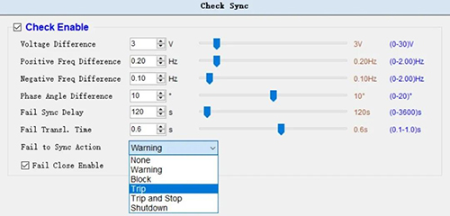
The control module waits for gensets and the mains power to meet the synchronization requirements, it will send out the mains power closing signal. After detecting the feedback signal of mains power switch-on, it will immediately send out the mains power switch-off signal, the power supply indicator lights off, the mains power is on-load, the mains power supply indicator lights on, and the “high-speed heat dissipation delay” begins to enter the shutdown process.
The conversion flow chart is as follows

Synchronous switching typical application diagram
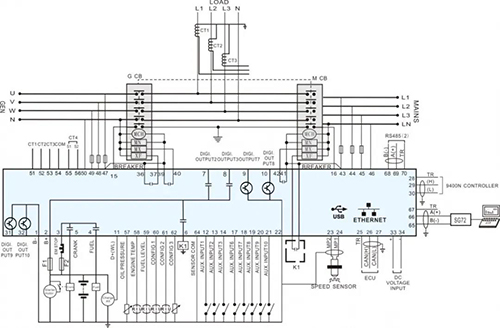
Note: Breakers (such as frame circuit breakers) that can close simultaneously should be used.
Parameter settings
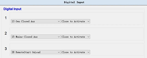
Note: the control module shall be set and conected the auxiliary contact signals to power generation switch closing and mains power switch closing, so as to judge the position state of switch-on and switch-off.
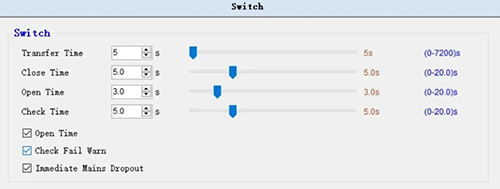
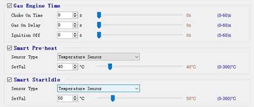
Switch-on/Switch-off time and on-off state detection time
Available for gas unit
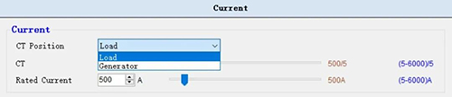
The position of current transformer can be defined
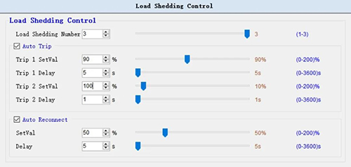
Three non-essential loads (NEL) settings
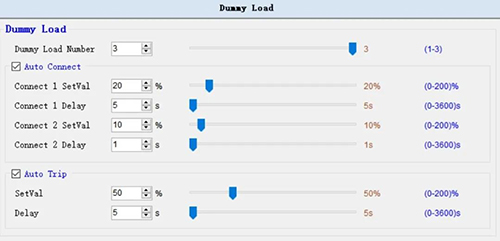
Three dummy loads settings
Cloud monitoring settings

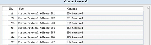
Communication protocol customization
It will be continued… Next chapter we will introduce the powerful built-in PLC functions of HGM9420N/LT.