
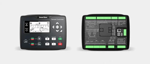
 In the previous three chapters, we respectively introduced the powerful display features of HGM9420N/LT (with 16 built-in languages), as well as the various extension, synchronization switching, communication protocol customization, NEL((non essential load), dummy load, cloud monitoring, etc. This chapter we will introduce the PLC function of the control module.
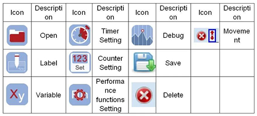
The PLC editing interface is shown as follows
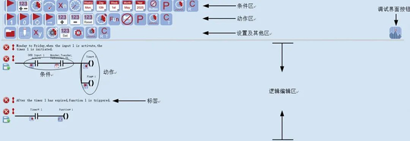
PLC elements: condition elements, action elements, settings and other areas
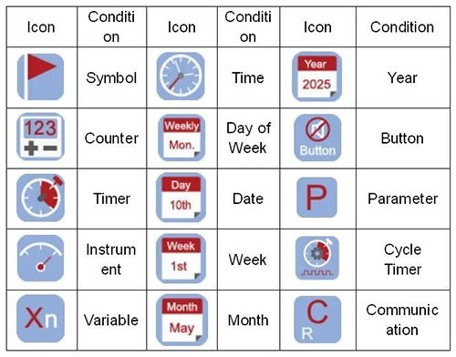
1. The conditional elements are shown in the following table
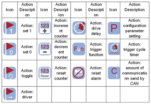
2. The action elements are shown in the following table
3. Setting and other areas
Logic Introduction
1. “Or” logic diagram
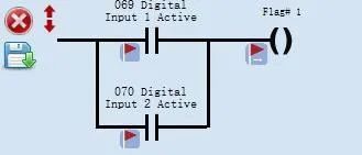
Description: either the input port 1 or the input port 2 is effective, the mark 1 is set to 1; otherwise the mark 1 is set to 0.
2. “And” logic diagram
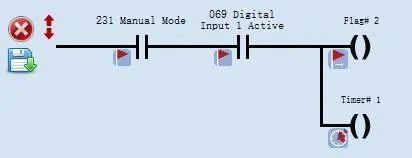
Description: when the control module is in manual mode and the input port 1 is effective, mark 2 is set to 1 and the timer 1 begins to counting; Otherwise mark 2 is set to 0, timer 1 reset.
3. Combinational logic example diagram
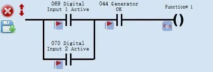
Description: either “input port 1” or “input port 2” is effective, and “normal output of power generation” is effective, triggering ” performance function 1″.
Applicaion Examples
Example 1: Engie Oil Prelubrication
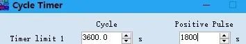
Engine Oil prelubrication function requirements: when it is standby, output 0.5 hour, stop output 0.5 hour; output during preheating, not during other periods.
1. The PLC logic diagram is as follows
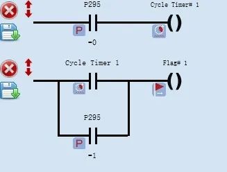
Description: P295 engine state parameter, 0: stands for “standby”; 1: stands for “preheating”.
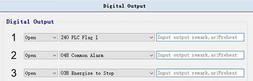
2. The settings of the control module output ports are as follows
Example 2: Automatic clear stop alarm
Requirements: when the genset is in automatic mode, after the remote start (on-load) input is disconnected, it will automatically clear the alarm.
1. The PLC logic diagram is as follow
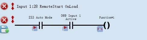
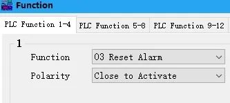
2. The control module input port is set as follows
![]()
Example 3: Modify the configuration parameters of successful crank conditions
Requirements: the successful crank condition of the unit is power generation + oil pressure. For the first start, the crank condition should be changed to power generation because crank cannot be judged accurately according to the oil pressure. For the second or the third start, the crank condition should be changed to power generation + oil pressure.
1. The PLC logic diagram is as follows
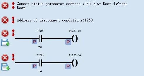
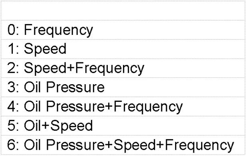
2. Description of successful crank
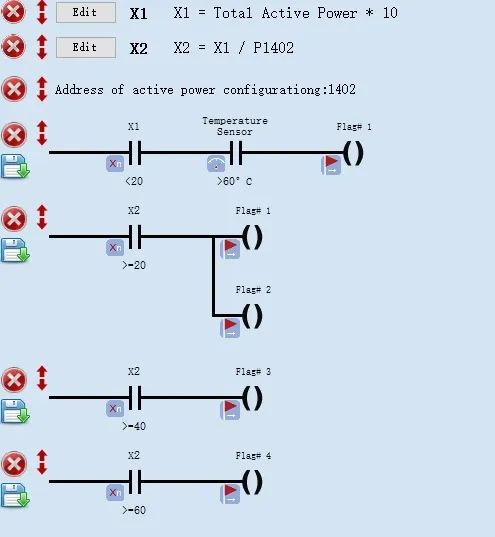
Example 4: Mutiple fans control
Requirements: when the percentage of the unit’s on-load power is less than 20% and the engine temperature is greater than 60℃, Fan 1 outputs. When the percentage of the unit’s on-load power is equal or great than 20%, Fan 1 and Fan 2 output; when the percentage of the unit’s on-load power is equal or great than 40%, Fan 1, 2 and 3 output; when the unit’s on-load power percentage is equal or great than 60%, Fan 1, 2, 3 and 4 output.
1. The PLC logic diagram is as follows:
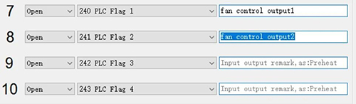
2. The settings of the control module output port are as follows
The PLC function of HGM9400N could also realize data acquisition and logic control with CAN interfaces modules (chargers, HAT series control modules, etc.) by customizing CAN communication configuration quantity.
It will be continued…
We will introduce functions and usage of the Host USB interface next time.