
This case is the renovation project of a domestic factory
1. Renovation Reasons
1) The eight gensets used other brands of parallel system, but they often failed to connect every time they needed to generate power in parallel. And after parallel connection, the load distribution is uneven, and the genset will stop due to overload.
2) After each mains power failure, genset shall be started manually. The operator on duty in the high-voltage distribution room turns on the switch, and the mains switch in the low-voltage distribution room does not lose voltage and trip. The operator on duty also needs to open the mains switch first and then close the generator switch. The process is cumbersome and not timely and safe.
2. Site Overview
The original emergency power of this factory is divided into two phases, with a total of eight gensets. The first phase is 500kW*4 gensets and the second phase is 800kW*4 gensets. Low-voltage distribution room is divided into five phases, each of which is powered by two mains transformers for two loads, for a total of 10 loads. The layout of the generator room and distribution room is shown in Figure 1.
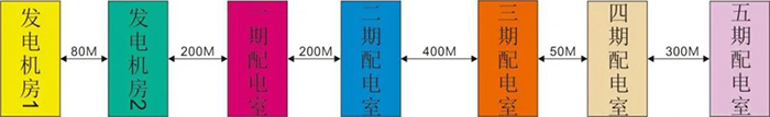
Fig.1 Layout of the Generator Room and Distribution Room
3. Renovation Scheme
The renovation project is divided into two stages:
1) Parallel control of 8 gensets by HGM9510.
2) Transfer 10-way emergency power cabinet and 10-way mains power cabinet into grid-connected control power by HGM9560.
Considering the long distance from the generator room to the low-voltage distribution room, long-distance transmission of MSC communication will cause data loss or abnormal communication. Therefore, the SGCAN300 CANBUS relay module is selected to convert MSCCAN signals into optical fiber signals for long-distance transmission. Eight SGCAN300 modules are selected for this project.
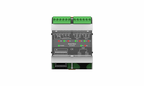
Fig.2 SGCAN300 CANBUS Relay Module
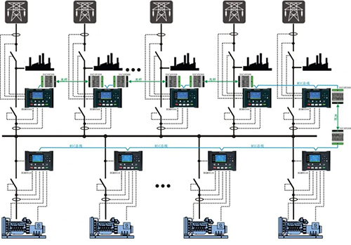
Fig.3 Typical Application of MSC1 and Optical Fiber Conversion

Fig.4 Typical Application of Multi-unit Parallel and Multiple Mains Grid-connection
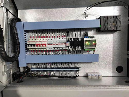
Fig.5 Installation and Connection Diagram of SGCAN300 in the Cabinet
4. Result of the Renovation
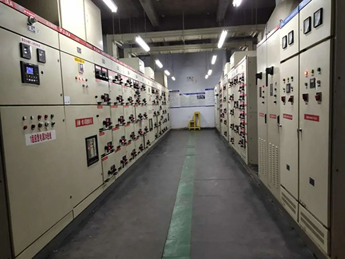
Fig.6 Distribution Room 1
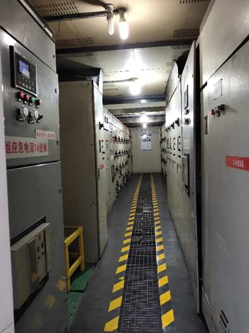
Fig.7 Distribution Room 2
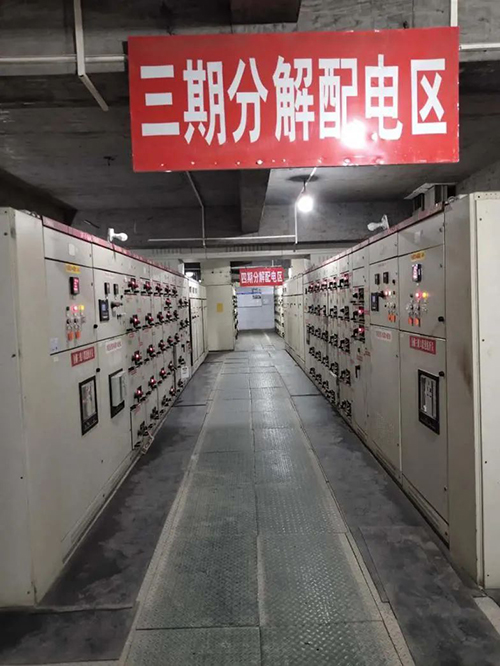
Fig.8 Distribution Room 3、4
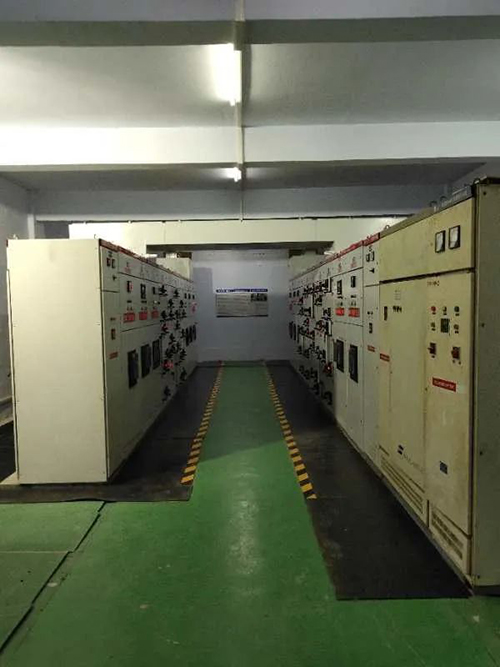
Fig.9 Distribution Room 5
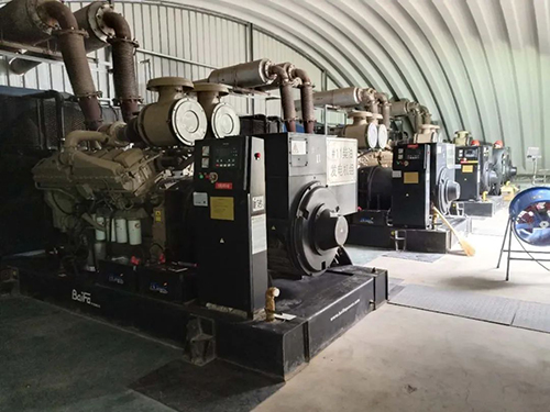
Fig.10 Generator Room 1
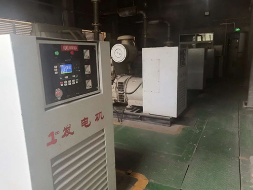
Fig.11 Generator Room 2